 cad-agent.
Engineering formulas
cadagent.formulas holds the closed-form equations that 3D-printed mechanisms keep needing: beams and snap arms,
torsion bars, springs, screws, four-bar and five-bar linkages, wall conduction and fan operating points. Agents call it from Python
instead of re-deriving the equations. The website's demonstrations call a browser port of the same functions, and the
two are tested against one set of golden vectors, so a demo never shows a number an agent would not get. Every
function states its SI units and its validity limits, and cites its source by author, title, edition and section.
Try it: the snap-arm explorer
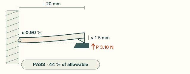
The explorer (<cad-cantilever>, also on Snap fits) runs the browser port
of snap_arm. Sliders set the length, root thickness, width and deflection, and you pick the material and print
direction. The beam bends along its computed curve, coloured by strain, with the root strain, force and pass or fail
against the filament's allowable strain.
Try it: the four-bar animator
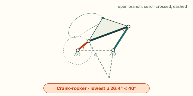
The animator (<cad-fourbar>, also on Linkages) runs the browser
port of grashof, fourbar_input_limits, fourbar_angles and transmission_angle. Sliders set the four links. The
crank turns, or rocks and stops where the linkage locks, on the assembly you pick, with the other assembly dashed. The
chart plots the transmission angle over a turn of the input against the 40° guideline. Rigid links on ideal pins,
position only.
Try it: the fan-curve explorer
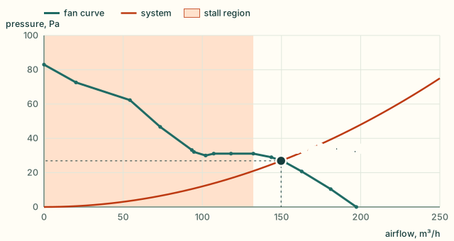
The explorer (<cad-fan-curve>, also on Airflow and fans) runs the browser
port of fans_in_parallel, fans_in_series, system_coefficient, fan_operating_point and fan_stall_flow on a
real fan's datasheet curve. Set the supply voltage, the pressure the enclosure needs at 100 m³/h, and one to four
fans in parallel or in series. The dot marks the operating point; the shaded band is the fan's stall region.
Two more explorers run the same port: the torsion-snap explorer
(torsion_snap_bar: a rectangular bar twisted by a lever) and the
screw-boss explorer (screw_boss: a thread-forming screw tightened
in a printed boss).
Limits
- A closed form is not proof of fit or strength. Each result holds only inside the limits it states. A printed part is weaker across its layers than any isotropic formula assumes, and creeps under a held load. Print the part and measure it.
- Small deflection and linear elasticity. These hold for every beam, torsion and spring formula here. For large
deflections, contact or plastic strain, use FEA (
cadagent.simulation.fea) and a test. - Screws. Torque gives preload to about ±25 % even with a known nut factor; in plastic the factor is unknown until measured. Thread stripping assumes even load sharing, which real threads do not have.
Why it is built, not adopted
We looked before writing anything. Each closed form here is a few lines long. The browser has to compute exactly what the Python does, and a Python dependency cannot be mirrored in a web page. CI's core job installs only PyYAML and NumPy. So the equations are written out here and tested against their sources. Beyond them, use fluids and ht for duct losses and convection, pint for unit-checked quantities, SymPy to derive new closed forms, and pylinkage for linkage synthesis.
The projects we surveyed, and what is reused from this repo
- fluids and ht by Caleb Bell (MIT):
pipe and duct losses, fittings, and hundreds of convection correlations. When a design needs a Nusselt number or a
duct loss coefficient, use them.
ht.conduction.k_to_Ris the same plane-wall resistance aswall_resistancehere. Our composite wall with surface films follows the same series-resistance layout asht's cylindrical version. - pint (BSD-3) for callers who want unit-checked quantities. These functions take plain SI floats, so the browser port can match them.
- SymPy (BSD-3) for deriving new closed forms. The tapered-arm integrals here were done by hand and checked numerically in the tests.
- pylinkage (MIT) for linkage synthesis and optimisation; here only position analysis.
- me-toolbox (MIT, by Omri Stein) for Shigley-style springs, fasteners and fatigue. It was read for scope. Its author describes it as a personal tool, and it pulls in SymPy.
- Reused from this repo, never forked:
- The snap-arm functions call
cadagent.mechanical.compliant.snapfit, so they matchcad-agent snapfitexactly. - The demo's materials come from
cadagent.mechanical.compliant.allowables. - The straight-line fan curve is the same model as
cadagent.thermal.heatsink.FanCurve. A test checks that the two solvers find the same operating point.
- The snap-arm functions call
How the sources, the Python, the golden vectors and the browser port connect:
Drawing diagram…
Scroll sideways to see the full diagram →
Diagram source
flowchart TD
S["Books, guides, standards<br/>Roark · Shigley · Covestro · Norton · Bulten<br/>Incropera · White · ISO 68-1, 898-1"] --> P["cadagent.formulas<br/>(Python, SI, cited)"]
C["cadagent.mechanical.compliant<br/>snapfit · allowables"] --> P
P --> A["agents<br/>catalogue() · snap_arm() …"]
P --> V["tools/formula_vectors.py<br/>golden vectors · demo materials"]
V --> J["kit/formulas.js<br/>(browser port)"]
J --> D["<cad-cantilever> · <cad-fourbar> · <cad-fan-curve><br/><cad-torsion-snap> · <cad-printed-boss>"]
classDef here fill:#fffdf5,stroke:#173d3c,color:#173d3c
classDef near fill:#eef1e4,stroke:#6f8a80,color:#173d3c
classDef out fill:#ffe1cc,stroke:#bd3a12,color:#173d3c
class P,V,J here
class S,C near
class A,D out
What it computes
SI units throughout: metres, newtons, pascals, kelvin, watts, radians, m³/s. A strain is a fraction (0.02 = 2 %).
All 48 functions in catalogue(): what each computes, its source and where it is valid
Table 38 rows: Function, What, Source, Valid within
| Function | What | Source | Valid within |
|---|---|---|---|
rect_second_moment |
I = b h³ / 12 | Roark 8th ed., Table A.1 | solid rectangle |
cantilever_tip_deflection |
y = F L³ / 3 E I | Roark 8th ed., Table 8.1, case 1a | Euler–Bernoulli, small deflection |
beam_stiffness |
3, 12, 48, 192 E I / L³ (cantilever, guided, simply supported, fixed–fixed) | Roark 8th ed., Table 8.1 | point load; slender beam |
cantilever_shape |
the deflected curve, constant or tapered arm | Roark 8th ed., Section 8.1, integrated exactly | end load |
cantilever_strain_profile |
surface strain along the arm over the root's | Roark 8th ed., Section 8.1 (σ = M c / I) | end load |
cantilever_thickness_profile |
thickness along the arm (design 2 tapers to h/2) | Covestro guide, Table 1 | linear taper |
cantilever_taper_factor |
exact k in y = k ε L² / h: 2/3, 1.0904, 0.8552 | Roark, integrated; Covestro Table 1 prints 0.67, 1.09, 0.86 | rectangle |
snap_root_strain |
ε = y h / (k L²), the guide's factors | Covestro guide, Table 1 (via snapfit) |
small deflection, one part rigid |
snap_deflection_force |
P = (b h² / 6) Es ε / L | Covestro guide, Table 1 (via snapfit) |
secant modulus at that strain |
snap_arm |
strain, force, stiffness, pass/fail, permissible deflection | Covestro guide, Table 1 (via snapfit) |
a pass has no extra margin |
shear_modulus |
G = E / 2(1 + ν) | Roark 8th ed., Section 2.2 | isotropic only |
torsion_constant_round, torsion_constant_rect |
K for solid, hollow and rectangular bars | Roark 8th ed., Table 10.1 (solid and hollow concentric circular, solid rectangular sections) | Saint-Venant torsion; the rectangle within 0.5 % |
torsion_shear_stress_round, torsion_shear_stress_rect |
peak shear stress | Roark 8th ed., Table 10.1 | away from ends and steps |
torsion_bar_twist, torsion_bar_stiffness |
θ = T L / K G, T / θ = K G / L | Roark 8th ed., Section 10.1 | constant section |
torsion_shear_strain_rect |
peak shear strain from the twist, γ = θ K (τ / T) / L: the section alone sets it | Roark 8th ed., Table 10.1 | within 0.8 % of the series |
torsion_snap_bar |
a rectangular torsion snap: shear strain against the guide's (1 + ν) ε, torque, force at the lever, permissible twist | Covestro guide, Section C; Roark 8th ed., Table 10.1 | small twist (it flags the trapeze effect past a tenth of the torque); isotropic G, so the force is an upper bound |
spring_index, spring_rate |
C = D / d, k = G d⁴ / 8 D³ Na | Shigley 10th ed., Sections 10-1, 10-3, Eqs. (10-1), (10-9) | 4 ≤ C ≤ 12; 15–85 % of travel |
bergstrasser_factor, spring_shear_stress |
K_B = (4C + 2)/(4C − 3), τ = K_B 8 F D / π d³ | Shigley 10th ed., Sections 10-1, 10-2, Eqs. (10-5), (10-7) | static, round wire |
preload_from_torque, torque_for_preload |
F = T / K d, with NUT_FACTORS |
Shigley 10th ed., Section 8-8, Eq. (8-27), Table 8-15 | ±25 % at best |
nut_factor |
K from thread and collar friction, at any flank angle (60° by default) | Shigley 10th ed., Section 8-8, Eq. (8-26) | collar at 1.25 d; ISO pitch diameter |
tensile_stress_area |
As = π/4 (d − 0.9382 p)² | ISO 898-1:2013; Shigley Table 8-1 | ISO metric |
thread_shear_areas, thread_strip_force |
0.75 π D1 Le (screw), 0.875 π d Le (hole) | ISO 68-1:1998 basic profile | even load sharing, no tolerances |
thread_radial_pressure |
the flanks' outward push, p = F tan(α / 2) / π d Le | Shigley 10th ed., Section 8-2 | frictionless flank, even load |
boss_hoop_stress |
hoop stress at the bore, p (D² + d²) / (D² − d²) | Shigley 10th ed., Section 3-14 | Lamé cylinder, isotropic |
screw_boss |
a thread-forming screw in a boss: clamp band, strip force and torque, the tightening window, hoop stress, boss proportions | Covestro, Self-tapping screws for thermoplastics (2016-04), Section A; Bulten, DELTA PT brochure (2025), p. 7 | the drive torque is measured, not computed, and makes no clamp: unmeasured, the clamp band allows for up to T / 1.2 of it |
grashof |
Grashof class, whether the input crank turns fully, and the inversion (crank-rocker, double crank, rocker-crank, double rocker, triple rocker) | Norton 5th ed., Chapter 2 | rigid links |
fourbar_angles |
coupler and output angles, open or crossed | Freudenstein (1955); Norton 5th ed., Chapter 4 | position only; a gap under 1e-12 of the longest link counts as closed |
transmission_angle |
angle between coupler and rocker | Norton 5th ed., Chapter 4 | position only; the same closing test |
fourbar_input_limits |
the input angles where coupler and rocker fold or stretch into line and the linkage locks | Norton 5th ed., Chapter 4 (toggle positions) | position only; the same closing test |
fivebar_point |
a five-bar's tip from its two crank angles, on either assembly | Gonçalves, Carvalho and Santos (COBEM 2009), Section 2.2, after Liu, Wang and Zheng (2006) | position only; a crank of 0 makes it a four-bar |
fivebar_inputs |
the two crank angles that put the tip at a point, on any of the four working modes | Gonçalves et al. (2009), Section 2.1 | position only; the tip inside both arms' reach |
fivebar_jacobians |
how near the five-bar is to a lock (distal links in line) or an arm's edge (crank and distal link in line), and the transmission angle | Gosselin and Angeles (1990) | first order: where a singularity is, not a force |
wall_resistance, film_resistance |
R = L / k A, R = 1 / h A | Incropera 7th ed., Section 3.1.2, Eqs. (3.6), (3.9) | steady, 1-D |
wall_heat_flow |
layers and films in series: heat flow and every face temperature | Incropera 7th ed., Section 3.1.3 | no contact resistance |
fan_curve_line, system_coefficient |
the datasheet fan line; k in Δp = k Q² | White 7th ed., Section 11.5 | same air density |
fans_in_series, fans_in_parallel |
identical fans: pressures add at one flow, flows add at one pressure | White 7th ed., Section 11.5 | no interaction losses |
fan_stall_flow |
the flow at the peak that ends the curve's last rise: below it, the stall region | White 7th ed., Section 11.5 | read from the curve's points |
fan_operating_point |
fan curve against Δp = r Q + k Q², solved exactly per segment; flags more than one crossing (unstable) and a point in the stall region | White 7th ed., Section 11.5 | steady flow |
fx.catalogue() returns the same list as data, with each function's units, limits and full citation, so an agent
can find the formula it needs without reading the source.
from cadagent import formulas as fx
arm = fx.snap_arm(length=0.020, thickness=0.0016, width=0.006, deflection=0.0015,
                  modulus=2.703e9, allowable_strain=0.020)       # CoPA, along the layers
arm["strain"], arm["force"], arm["passes"]                        # 0.0090, 3.1 N, True
fx.preload_from_torque(torque=0.5, diameter=0.003)                # 833 N with K = 0.2
fx.fan_operating_point(fx.fan_curve_line(15.2, 0.0108), k=2e6)   # flow, pressure, stability
In the browser, kit/formulas.js exports the functions the demos use (snapArm, cantileverShape,
cantileverStrainProfile, fourbarAngles, fanOperatingPoint and the others in the golden vectors) in the same SI
units. kit/formulas-data.js carries the demos' data: the printed filaments, and the fan curves of
cadagent.thermal.fans.
Tests that keep it honest
tests/test_formulas.py checks each function against a published value or an independent derivation written out
in the test.
What each family is tested against: beams, torsion, springs, screws, linkages, heat and air
- Beams.
- Beam stiffness by the direct stiffness method.
- The tapered-arm curves by numerical integration, and the Covestro Table 1 factors as the exact integrals rounded.
- Example I of the guide in SI units, and agreement with
cad-agent snapfitto 1e-12.
- Torsion.
- Rectangular sections against the Saint-Venant series (within 0.5 %, the worst at aspect 1.145), and against the tabulated coefficients in Shigley, Section 3-12.
- The peak shear strain against the series (within 0.8 %, the worst at aspect 1.136), and its thin-strip limit.
- The guide's torsion snap as the same mechanics; the rectangular snap's torque, force and permissible twist from
first principles (
tests/test_torsion_snap_boss.py).
- Springs.
- The rate derived from the wire as a torsion bar.
- Bergsträsser against Wahl.
- Screws.
- The ISO stress areas against their tabulated values.
- K ≈ 0.2 from Eq. (8-26) at a friction of 0.15.
- The 0.75 and 0.875 shear-area factors derived from the ISO 68-1 profile.
- The flank's radial push from its statics, and Lamé's hoop stress against the equilibrium of half the ring.
- Linkages.
- Loop closure, and an independent circle-intersection construction, at every input angle.
- Kites (a = b, c = d) and near-kites, every 0.1 degree, where the textbook root divides 0 by 0.
- Parallelograms and other change-point linkages, every 0.1 degree and every 1e-9 rad near 0 and 180 degrees, where the two branches meet and round-off can push the discriminant below 0. Each branch must be the one asked for.
- The input's limit angles on linkages whose crank cannot turn fully, where the linkage closes in one position.
fourbar_input_limitson every four-bar with links 1 to 6: the input turns fully exactly whengrashofsays so, andfourbar_anglescloses exactly inside the limits.- Norton's Example 4-1.
- The five-bar (
tests/test_linkages.py) against Liu, Wang and Zheng's direct and inverse kinematics as Gonçalves et al. print them, a line and a quadratic rather than two circles, on two symmetric 5Rs every 15 degrees; the tip's reach against the two annuli; the Jacobians against finite differences; and a four-bar as a five-bar without a second crank againstfourbar_angles.
- Heat and air.
- The composite wall face by face.
- The fan point against the quadratic root and against
cadagent.thermal.heatsink.operating_point. - A stall dip flagged unstable, and the stall region's edge on dips and flat tops.
- One fan, two in series and two in parallel solved by hand, and where series and parallel give the same air.
- Every operating point the ebm-papst datasheet tabulates, found again from its curves and system curves.
tools/formula_vectors.py --check fails when the committed golden vectors or the demo's material table no longer
match the Python. tests/webkit-formulas.test.mjs runs the browser port on those vectors to 1e-12.