 cad-agent.
Compliant mechanisms and single-part joints: references, equations, allowables, process effects (2026-10-31)
For Valpatel/cad-agent #94 (compliant-mechanism engineer), #95 (calculators), #97 (pitfalls), #99 (process profiles).
Extends research/landscape.md (2026-10-24) and research/simulation-tools.md (2026-10-26). Neither covers this field.
How this was checked. "Read" means the text was pulled from the PDF or page on 2026-10-31 (pdftotext or the page's
own Markdown) and the number is quoted from it. (s) means the number comes only from a search-engine snippet of the
page, not from reading the page. (u) means unverified: from memory, or from a source that could not be opened.
[derived] means I calculated it from cited inputs; the method is stated beside it. Citation keys such as [BAY] are
listed in §10.
1. Feature catalogue
Table 15 rows: Feature, Use it when, Governing equations / reference, Typical failure modes, …
| Feature | Use it when | Governing equations / reference | Typical failure modes | Process notes |
|---|---|---|---|---|
| Cantilever snap: constant section, tapered to h/2, or width tapered to b/4 | One-off or occasional assembly of a lid, cover or panel; you want the joint stress-free once seated | Bayer Table 1 [BAY]: y = K·ε·l²/h, P = b·h²·E_s·ε/(6l), W = P(μ+tanα)/(1−μ·tanα). DuPont: S = FLc/I, y = FL³/3EI [DUP]. See §2 | Root crack at a sharp fillet; strain over the allowable because the undercut was guessed; creep loss of retention when left deflected; weld line at the hook [DUP] | Moulded: a 90° undercut needs a side core or a slot in the part [DUP]. FDM: deflect within the layers and never stack the beam in Z [KLA][HUBS-SF] |
| U-shaped / L-shaped snap | Not enough straight length for the strain: folding the arm makes it longer in the same envelope | Bayer recommends a curved-beam analysis and gives no closed form [BAY]. BASF manual pp. V-1…V-4 [BASF] (s). A Fusion add-in implements U-shaped and overlay snaps [F360SF] | Strain peaks at the inner radius of the U; the fold becomes a stress raiser | FDM: the U must lie flat in XY |
| Torsion snap | Release by pressing a lever; the hook rotates rather than bends | φ_pm[°] = (180/π)·γ_pm·l/r; γ_pm ≈ (1+ν)·ε_pm ≈ 1.35·ε_pm; P₁l₁ = P₂l₂ = γ·G·I_p/r, with I_p = πr⁴/2 for a round bar [BAY] (the PDF text is partly garbled; the form is standard torsion) | Shear fracture of the torsion bar; posts too weak | FDM: run the bar along a layer; posts in Z are weak in bending |
| Annular snap | Round, rotationally symmetric parts: caps, lamp covers, bearings | y_pm = ε_pm·d with one part rigid (halve the strain if both parts are equally flexible); P = y·d·E_s·X; X_N = 0.62·√[(d₀/d−1)/(d₀/d+1)]/{[(d₀/d)²+1]/[(d₀/d)²−1]+ν} (the square root is on the rendered page; pdftotext drops it; lamp cover: 1.69e-3, Bayer 1.7e-3); a groove far from the tube end needs up to 3× the force [BAY]. DuPont: hub-expansion force from interference stress and geometry factor W [DUP] | Hoop crack at a weld line [DUP]; an inseparable return angle needs a split-cavity mould [BAY] | FDM: a full ring is too stiff, so slot the collar into fingers [F360SF] |
| Living hinge | Lid and box in one part, many cycles, moulded PP/PE | Moulded PP: 0.012 in (0.30 mm) thick, about 0.060 in (1.5 mm) spacing, a 0.008 in reduction on the side it folds towards, and a 0.030 in radius on the tension side [PL-LH]. Land 1.5 mm, thickness 0.2–0.4 mm [PT-LH] (s). Strain ε = t·θ/(2L) under uniform bending [derived] | Cracks at once if not flexed while warm (K-resin) [PL-LH]; knit line across the hinge [PL-LH] | A 180° fold of 0.3 mm over 1.5 mm reaches ε ≈ 31 % [derived], which only orienting PP/PE survives. FDM PLA/PETG hinges are short-life: print them flat with lines across the hinge axis (u). BOSL2 living_hinge_mask models a printed hinge by layer height [BOSL2] |
| Leaf flexure / parallel-guided stage | Short-stroke guidance without backlash: probe mounts, stages, grippers | Small deflection: one leaf K_θ = EI/L under end moment; a fixed-guided leaf k = 12EI/L³, so two leaves give k = 24EI/L³ and σ_max = 3E·t·δ/L² [derived, beam theory]. Large deflection: PRBM γ = 0.85, K_Θ ≈ 2.65 for end force [PRB][CHEN-PRB] (s). References: Howell [HOW], Smith [SMITH] | Fatigue at the clamp; buckling under axial load; parasitic motion | FDM: leaves in XY, at least 2 perimeters, no infill in the leaf (u) |
| Notch hinge (circular, elliptical) | Precision pivots with small rotation | Paros & Weisbord 1965, simplified (t ≪ R): θ/M ≈ 9πR^½ / (2E·b·t^{5/2}) (u: the constant was not checked against the 1965 paper; see Lobontiu [LOB]) [PW] | Stress concentration at the throat limits the angle to a few degrees | Needs isotropic, notch-tough material; poor in FDM (the notch sits across layers) (u) |
| Cross-axis flexural pivot (CAFP) / cross-spring | Larger rotation than a notch, with less centre shift than a single leaf | Haringx 1949: the pivot point is near where the leaves cross and shifts with angle [HAR]. PRBM/CBCM model of CAFPs [CAFP]. The often-quoted K ≈ 8EI/L for leaves crossing at mid-length is (u) | Centre shift; stiffness depends on load direction [HAR] | FDM: leaves that cross in the XY plane print. Leaves crossing in Z need bridges (u) |
| LET joint (lamina emergent torsion) | A rotational joint cut from flat sheet: laser-cut, waterjet or planar-printed | Jacobsen, Chen, Howell, Magleby 2009 give the force-deflection equations: torsion bars and bending segments combined as series/parallel springs [LET]. The equations were not read here (the PDF is bot-blocked): (u) | Parasitic motion, so the off-axis stiffness is low [LET]; torsion-bar shear | Planar by design: printed flat in XY, or cut from sheet. BYU LET-joint chair model [BYU] |
| Bistable latch (curved beam) | Two stable states without a spring: switches, latches | Qiu cosine double beam, centrally clamped, second mode constrained: bistable when Q = h/t > 2.31; for Q ≥ 6, f_top ≈ 740·EIh/l³, f_bot ≈ 370·EIh/l³, d_mid = 1.33h, d_top ≈ 0.16h, d_bot ≈ 1.92h [QIU] (read) | Second-mode buckling with only one beam; asymmetric clamping; stress relaxation flattens the curve | FDM: the beams must lie in XY; the amplitude h must be ≥ several line widths |
| Detent (cantilever and bump, ball and spring) | Indexed positions, holding a lid open | Cantilever equations from §2. Holding force uses the same W formula with the return angle α′ in place of α [BAY][derived] | The bump wears; the holding force drifts with friction (the μ ranges in §4) | Printed bumps on sloped faces chatter across the stair-steps [KLA] |
| Spring tab (printed cantilever or serpentine) | Preload against a part, anti-rattle, battery contacts | Cantilever formulas; design for sustained strain well below the snap allowable (u) | Creep: a preload carried by a printed polymer relaxes. No study of permanently deflected printed snaps was found (§9) | A metal spring is safer for sustained load. static74's skill offers a printed/metal choice for every spring [S74] |
| Crush / press ribs | A press fit into a drafted or variable hole without tight tolerance | At least three undrafted ribs along the hole [PL-CR]; rib about 2.5 mm diameter with about 0.25 mm interference [RD-CR] (s) | Ribs shear off; hoop crack in a thin boss | Printed: no published values were found, so print a coupon. FDM ribs in Z are strong in shear |
| Print-in-place joint | Hinges and chains that come off the bed already assembled | XY clearance 0.2–0.4 mm for a 0.4 mm nozzle (forum and third-party guides, not official) [PIP]; FDM 0.5 mm, SLA/SLS/MJF 0.3 mm [HUBS-SF]. PrusaSlicer merges bodies closer than about 0.5 mm unless the slice-gap closing radius is changed [PIP-PS] (s) | Fused joint; elephant's foot locks the first layer | Make Z gaps a multiple of the layer height [PIP] (s). b123d-print's gap check fails solids closer than pip_clearance [B123] |
| Sheet-metal spring clip / tab | A metal latch or ground spring cut and bent from tempered strip | Beam formulas with the yield of the temper: 301 full-hard has UTS ≥ 1276 MPa, yield ≥ 965 MPa, elongation ≥ 9 % [ULB] (s). Associated Spring flat-spring design stresses (u, not found) | Cracks at the bend in hard temper; fatigue at the root | Protolabs: features within about 4T of a bend distort; tab width ≥ max(2T, 3.2 mm) [PL-SM]. Bend radius against temper (u) |
2. Snap-fit equations and worked examples for tests (Bayer guide, read)
Source [BAY]: Bayer MaterialScience, Snap-Fit Joints for Plastics – A Design Guide (26 pp). Covestro is the successor company and the issue cites the Covestro edition [COV]; the copy read here is the Bayer-branded PDF, and the Covestro edition prints the same equations and worked examples. Cite them, do not redistribute them.
- Undercut = deflection. Partially crystalline resins may be strained almost to yield in a single brief snap. Amorphous resins may be strained to about 70 % of the yield strain. Glass-filled resins (no yield point) may be strained to about half the elongation at break. For frequent separation, use about 60 % of the single-use value.
- Taper. A beam whose thickness falls linearly to h/2 (Table 1 design 2) allows more than 60 % more deflection than a constant section: y = 1.09·ε·l²/h. A constant section (design 1) has y = 0.67·ε·l²/h and a width taper to b/4 (design 3) has y = 0.86·ε·l²/h. These two constants are (u): Table 1 is an image in this copy. They agree with the 1.09/0.67 ≈ 1.63 ratio, and 0.67 is exact beam theory for a constant rectangular section (y = PL³/3EI with ε = PLh/2EI gives y = (2/3)·ε·l²/h) [derived]. The Covestro edition's worked examples print 1.09 (design 2) and the general-section 0.55 (design 2) in text (read). The polarised-light figure shows a constant-section arm with 46 % higher strain and 17 % more material than the optimum.
- Root fillet. Stress concentration levels off near R/h = 0.6, but a large radius makes a thick section that sinks. Use a compromise, and never less than 0.015 in (0.38 mm). DuPont's general rule is a fillet of t/2 and a corner of at least 0.020 in (0.5 mm) [DUP].
- Mating force: W = P·(μ+tanα)/(1−μ·tanα). E_s is the strain-dependent secant modulus, taken at the design strain.
| Gold test case | Inputs | Expected output [BAY] |
|---|---|---|
| Example I, tapered hook (design 2, rectangular section) | Makrolon PC; l = 19 mm; b = 9.5 mm; y = 2.4 mm; α = 30°; ε_pm = 4 % with design ε = ½ε_pm = 2 %; E_s(2 %) = 1815 MPa; μ = 0.5×1.2 = 0.6 | h = 1.09·0.02·19²/2.4 = 3.28 mm; P = 32.5 N; (μ+tanα)/(1−μ·tanα) = 1.8; W = 58.5 N |
| Example II, ring-segment hook (design 2, shape C) | Bayblend PC/ABS, frequent separation: ε = 0.6×2.5 % = 1.5 %; l = 25.4; r₂ = 20; r₁ = 17.5; h = 2.5; θ = 75°; K₂ = 2.67 (Fig. 10) | y = 1.64·K₂·ε·l²/r₂ = 2.11 mm. Cross-check: c₂ = 2.52 mm, y = 0.55·ε·l²/c = 2.11 mm |
| Annular lamp cover | Makrolon; d = 200; t = 2.5; undercut 2×1 mm (equal stiffness); α = 45° taken as 30° effective; E_s = 2200 MPa; d₀/d = 1.025 → X_N = 1.7e-3 | ε = 0.5 %; P = 748 N; W = 748×1.8 = 1346 N |
These three cases are the acceptance tests the issue asks for ("calculators reproduce the design guide's worked examples").
3. Allowable strain tables (moulded resin)
Bayer Table 2 [BAY] (read): short-term strain limits at 23 °C for a single assembly; use about 60 % for frequent separation.
| Resin | Single | Frequent (×0.6) |
|---|---|---|
| Apec high-heat PC | 4 % | 2.4 % |
| Bayblend PC/ABS | 2.5 % | 1.5 % |
| Makroblend PC blends | 3.5 % | 2.1 % |
| Makrolon PC | 4 % | 2.4 % |
| Makrolon PC, 10 % glass | 2.2 % | 1.3 % |
| Makrolon PC, 20 % glass | 2.0 % | 1.2 % |
DuPont Table 10.06 [DUP] (read): suggested allowable strain for lug-type snap fits.
| Resin | Used once (new material) | Used frequently |
|---|---|---|
| Delrin 100 (POM) | 8 % | 2–4 % |
| Delrin 500 (POM) | 6 % | 2–3 % |
| Zytel 101 (PA66), dry | 4 % | 2 % |
| Zytel 101, 50 % RH | 6 % | 3 % |
| Zytel GR (glass), dry | 0.8–1.2 % | 0.5–0.7 % |
| Zytel GR, 50 % RH | 1.5–2.0 % | 1.0 % |
| Rynite PET GR | 1 % | 0.5 % |
| Crastin PBT GR | 1.2 % | 0.6 % |
| Hytrel (TPC elastomer) | 20 % | 10 % |
- BASF Snap-Fit Design Manual, p. IV-4, has allowable strain and friction for eight resins, with worked examples for an Ultradur PBT grade and an Ultraform POM grade [BASF]. The values were not read: the tables are images, and only unofficial Scribd/studylib copies exist.
- Celanese/Ticona: a dynamic strain limit up to 70 % of the yield strain for resins with a yield point, and 60 % of that for repeated engagement [CEL]. These figures are (s): the OCR is garbled.
- Older Bayer table. Third-party skills quote ABS 4–6 % and PA 4–6 % "from the Bayer 1998 manual" [AGCAD]. That is (u): the copy read here has only the six Bayer rows above. Do not carry those values over without the original.
4. Friction coefficients (Bayer Table 3, plastic on steel; same-material factor in brackets) [BAY] (read)
PTFE 0.12–0.22 · PE rigid 0.20–0.25 (×2.0) · PP 0.25–0.30 (×1.5) · POM 0.20–0.35 (×1.5) · PA 0.30–0.40 (×1.5) · PBT 0.35–0.40 · PS 0.40–0.50 (×1.2) · SAN 0.45–0.55 · PC 0.45–0.55 (×1.2) · PMMA 0.50–0.60 (×1.2) · ABS 0.50–0.65 (×1.2) · PE flexible 0.55–0.60 (×1.2) · PVC 0.55–0.60 (×1.0).
5. FDM anisotropy: in-plane (X-Y) vs inter-layer (Z) data from manufacturer TDS (read)
All specimens were 100 % infill, ISO 527 / GB/T 1040. Z means pulled across the layers. Each row is the maker's current
edition, read on 2026-10-31 (#156). Where an earlier edition differs, cadagent.mechanical.compliant.allowables keeps both
and takes the cautious one per quantity (§6); the earlier values are under the chart.
Table 17 rows: Material (TDS version), E XY / Z (MPa), UTS XY / Z (MPa), Elong. at break XY / Z (%), …
| Material (TDS version) | E XY / Z (MPa) | UTS XY / Z (MPa) | Elong. at break XY / Z (%) | Z/XY strength | Z/XY strain | Source |
|---|---|---|---|---|---|---|
| PLA Basic, Bambu (V3.0) | 2580 / 2060 | 35 / 31 | 12.2 / 7.5 | 0.89 | 0.61 | [BBL-PLA] |
| PLA Matte, Bambu (V3.0) | 1960 / 1670 | 30 / 22 | 14.8 / 4.8 | 0.73 | 0.32 | [BBL-PLAM] |
| PolyLite PLA, Polymaker (V5.4) | 3427 / 3065 | 52.3 / 40.5 | 6.3 / 1.8 | 0.77 | 0.29 | [PM-PLA] |
| PETG Basic V3.0, Bambu (the reformulated filament; bars not said to be annealed) | 2780 / 2550 | 51 / 35 | 9.5 / 5.2 | 0.69 | 0.55 | [BBL-PETG3] |
| PETG Basic V2.0, Bambu (the earlier filament; annealed and dried 65 °C/8 h) | 1460 / 1120 | 48 / 39 | 11.2 / 5.7 | 0.81 | 0.51 | [BBL-PETG] |
| PETG HF, Bambu (V1.0) | 1810 / 1540 | 34 / 23 | 8.6 / 5.1 | 0.68 | 0.59 | [BBL-PETGHF] |
| PETG-CF, Bambu (V3.0) | 2460 / 1340 | 35 / 29 | 10.4 / 4.7 | 0.83 | 0.45 | [BBL-PETGCF] |
| PolyLite PETG, Polymaker (V5.4) | 2117 / 1899 | 50.8 / 42.8 | 8.4 / 3.3 | 0.84 | 0.39 | [PM-PETG] |
| ASA, Bambu (V3.0; annealed and dried 80 °C/12 h) | 2450 / 2120 | 37 / 31 | 9.2 / 4.6 | 0.84 | 0.50 | [BBL-ASA] |
| PolyLite ASA, Polymaker (V6.0, the same values as V5.4) | 2379 / 1965 | 43.8 / 32 | 6.7 / 1.65 | 0.73 | 0.25 | [PM-ASA] |
| PolyMide CoPA, dry (annealed 80 °C/6 h) | 2703 / 2209 | 78.0 / 45.8 | 12.7 / 1.3 | 0.59 | 0.10 | [PM-COPA] |
| PolyMide CoPA, wet (6.16 % moisture) | 724 / 660 | 34.3 / 13.7 | 13.2 / 1.7 | 0.40 | 0.13 | [PM-COPA] |
| Fiberon PA6-CF20, dry (annealed 100 °C/16 h; V1.1) | 8637 / 3760 | 109.3 / 54.0 | 2.1 / 1.9 | 0.49 | 0.90 | [PM-PA6CF] |
| Fiberon PA6-CF20, wet | 2508 / 1056 | 54.7 / 25.5 | 7.0 / 6.7 | 0.47 | 0.96 | [PM-PA6CF] |
| PA6-CF, Bambu (V3.0, dry; annealed and dried 80 °C/12 h) | 4430 / 2170 | 102 / 48 | 5.8 / 3.7 | 0.47 | 0.64 | [BBL-PA6CF] |
| TPU 95A HF, Bambu (V1.0) | 9.8 / 7.4 | 27.3 / 22.3 | >650 / >480 | 0.82 | — (both lower bounds) | [BBL-TPU] |
| PolyFlex TPU95, Polymaker (V5.4) | 33.6 XY (ISO 37) | — | 551 XY | — | no Z data | [PM-TPU] |
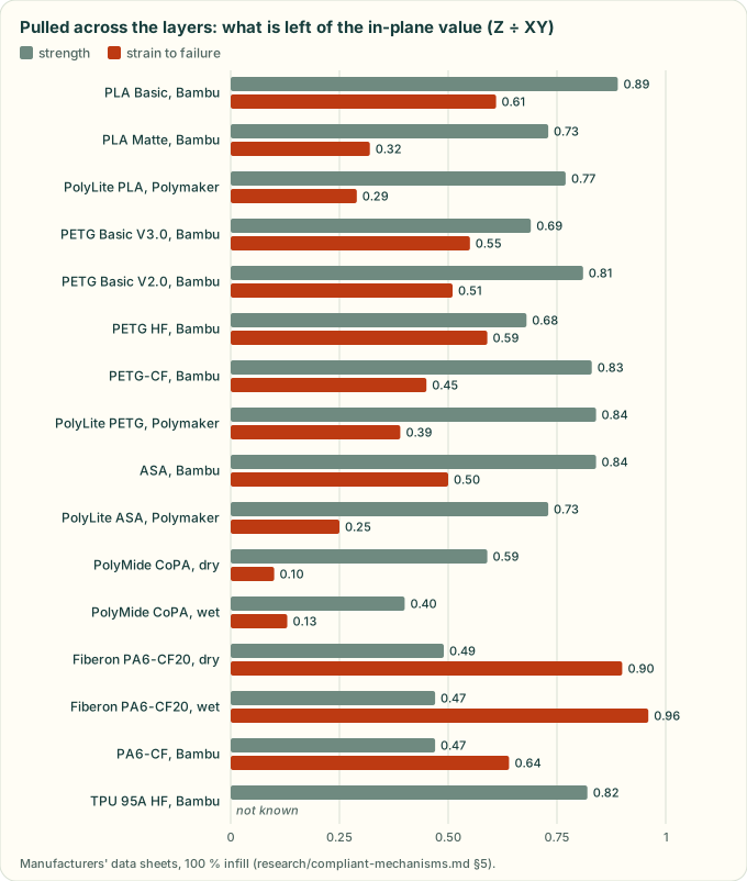
Drawn from the table above by tools/research_figures.py (a test keeps the two in step). Pulled across the layers,
most filaments keep 60–90 % of their strength but much less of their stretch; Polymaker's carbon-filled PA6 is the
exception. TPU's strain ratio is not drawn: both its samples outlasted the test (>650 / >480 %), and a ratio of two
lower bounds says nothing.
Earlier editions. Bambu's V2.0 sheets (a reseller's copies: [BBL-PLA-V2], [BBL-PLAM-V2], [BBL-PETGCF-V2], [BBL-ASA-V2]) tested the same filaments and gave higher strengths: PLA Basic E 2680 / 2160 MPa and UTS 39 / 35 MPa; PLA Matte UTS 32 / 25 MPa and elongation 32.8 / 4.8 %; PETG-CF UTS 59 / 38 MPa; ASA UTS 52 / 35 MPa (the other values as V3.0). PETG Basic is two filaments, both in the table: V3.0's text calls it "the all-new Bambu Lab PETG Basic … The refined formula", and its bars are not said to be annealed (it advises against annealing PETG Basic), where V2.0's were annealed and dried at 65 °C for 8 h. A spool does not say which it is.
Reading the table:
- Strain to failure across the layers falls far more than strength. For PLA, PETG, ASA and CoPA the Z/XY strength ratio is 0.40–0.89 (0.59–0.89 without wet CoPA), but the Z/XY elongation ratio is 0.10–0.61. How much of the allowable this costs depends on which limit governs in §6. Where 0.7·UTS/E governs, or the two limits are close (PLA, PETG, Bambu ASA), the allowable across the layers is 75–100 % of the in-plane value. Where half the elongation at break governs across the layers (Polymaker ASA, CoPA) it falls to 26–64 %. The orientation rule below applies either way: the notch effect of layer lines is not in a tensile test.
- Allum et al. 2020 found that the bond between layers has bulk strength in printed PLA. Their explanation for the anisotropy is the extruded-filament geometry: grooves and voids concentrate strain, not incomplete bonding [ALL]. So layer lines act like notches, and Bayer's "half the elongation at break" rule for materials without a yield point is the right model for Z.
- Carbon fibre lowers in-plane strain (PA6-CF20: 2.1 % XY dry; Bambu PA6-CF 5.8 %), so CF grades are poor for snap fits even though they are strong. Bambu's PA6-CF keeps 64 % of its elongation across the layers, against 90–96 % for Polymaker's PA6-CF20, so the fibre's levelling effect is not general.
- Moisture. Water-saturated PA6-CF20 bars (5.30 % moisture) keep 0.50 / 0.47 of the dry strength but only
0.29 / 0.28 of the dry modulus (XY / Z) [PM-PA6CF]. No sheet read gives a printed CF-PA6 in room air. BASF's moulded PA6
datasheets give dry / conditioned values ("cond."; equilibrium moisture at 23 °C / 50 % r.h. is 2.7–3.2 % unfilled,
1.9–2.3 % with 30 % glass): unfilled PA6 keeps 0.31 of its tensile modulus (Ultramid B3S HP R01, 1000 / 3200 MPa, a
preliminary sheet) and 0.50 of its yield stress; 30 % glass-filled PA6 keeps 0.58 of its modulus and 0.57 of its
strength (Ultramid B3EG6 SI, 5650 / 9700 MPa, 105 / 185 MPa at break) [BASF-B3S][BASF-B3EG6]. Bambu's PA6-CF takes
up 2.35 % at 25 °C / 55 % RH [BBL-PA6CF]. So
cadagent.simulation.fea's humid PA6-CF rows take Polymaker's saturated ratios for both modulus and strength. That is a judgement for the cautious end, not a measured room-air value: a filled print plausibly sits between the unfilled and glass-filled moulded ratios (0.31–0.58), so in room air these rows may be up to about 2x too soft. That is cautious for deflection, but a force or stress worked out at a given travel reads low (#157). - Orientation rule. Lay the flexing member in XY and keep the joining direction independent of the bending direction. A cantilever built along Z is "poor", and the stair-step notches add stress concentration [KLA]. Hubs: avoid Z-built cantilevers; MJF root at least 1 mm thick; fillet ≥ 0.5×root thickness; width ≥ 5 mm [HUBS-SF]. Schreiber et al. 2021 found that moulding guidelines transfer poorly to FDM and SLS [SCH] (s).
HP Jet Fusion 5200 (MJF), XY / Z [HP] (read):
| Material | UTS (MPa) | Elong. at yield (%) | Elong. at break (%) |
|---|---|---|---|
| PA 12 | 50 / 50 | 10 / 8 | 17 / 9 |
| PA 11 | 54 / 54 | 25 / 20 | 40 / 25 |
| PA 12 GB | 31 / 30 | 8 / 4 | — |
| PP | 29 / 29 | 9.5 / 9.5 | 20 / 14 |
MJF is isotropic in strength but not in strain.
SLA (Formlabs).
- Tough 1500 V2: E about 1460 MPa, elongation 155 % [FL-T1500] (s).
- Formlabs does not recommend Tough 2000 for living hinges [FL-T2000].
- No XY/Z breakdown was found, so SLA isotropy is (u).
6. Printed allowable strain: a starting rule to be confirmed by coupons [derived]
Rule:
- Single assembly: ε_single = min(0.7·UTS/E, 0.5·ε_break), applied separately to XY and Z values. 0.7·σ/E is Bayer's amorphous rule using UTS/E as a lower bound on the strain at maximum stress. 0.5·ε_break is Bayer's no-yield rule.
- Repeated assembly: ε_repeat = 0.6·ε_single.
- Never exceed the moulded value for the same polymer family (§3).
- In Z, use min(Z, XY).
- Bayer's own example designs at ½ε_pm, which is a factor of 2.
- Where a filament has more than one edition of its sheet, apply rules 1–4 to each edition's own values and take the lowest allowable; take the mating force from the highest modulus and the retention force from the lowest (each the cautious side; both above the secant modulus at the design strain, so retention stays optimistic) (#156).
Table 14 rows: Material (TDS), XY single / repeat, Z single / repeat, static74 skill, in-plane single / repeat / across layers [S74], …
| Material (TDS) | XY single / repeat | Z single / repeat | static74 skill, in-plane single / repeat / across layers [S74] | AgentCAD table, design value before its printing derate [AGCAD] |
|---|---|---|---|---|
| PLA (Polymaker) | 1.1 / 0.6 % | 0.9 / 0.5 % | 2.0 / 1.2 / ≤0.5 % | 1.2 % |
| PLA Basic (Bambu V3.0; V2.0 gave 1.0 %) | 0.95 / 0.57 % | 0.95 / 0.57 % | — | — |
| PLA Matte (Bambu V3.0; V2.0 gave 1.1 / 1.0 %) | 1.1 / 0.64 % | 0.92 / 0.55 % | — | — |
| PETG (Polymaker) | 1.7 / 1.0 % | 1.6 / 0.95 % | 3.6 / 2.1 / ≤1.0 % | 3.0 % |
| PETG Basic (Bambu V3.0, the reformulated filament: used) | 1.3 / 0.77 % | 0.96 / 0.58 % | — | — |
| PETG Basic (Bambu V2.0, the earlier filament) | 2.3 / 1.4 % | 2.3 / 1.4 % | — | — |
| PETG HF (Bambu V1.0) | 1.3 / 0.8 % | 1.0 / 0.6 % | — | — |
| PETG-CF (Bambu V3.0; V2.0 gave 1.7 %) | 1.0 / 0.60 % | 1.0 / 0.60 % | — | — |
| ASA (Polymaker) | 1.3 / 0.8 % | 0.8 / 0.5 % | 2.0 / 1.2 / 0.3–1.0 % | — |
| ASA (Bambu V3.0; V2.0 gave 1.5 / 1.2 %) | 1.1 / 0.63 % | 1.0 / 0.61 % | — | — |
| CoPA, dry (Polymaker) | 2.0 / 1.2 % | 0.65 / 0.4 % | 3–4 / 2 / ≤0.4 % | PA 6 % (moulded basis) |
| CoPA, wet | 3.3 / 2.0 % | 0.85 / 0.5 % | — | — |
| PA6-CF20, dry | 0.9 / 0.5 % | 0.9 / 0.5 % | — | — |
| TPU 95A | strain does not govern; size for force and retention | — | ≥10 % | — |
- The derived values are about half of static74's for PETG, which applied 70 % of an estimated yield strain. AgentCAD's 3.0 % is before its own printing derate. After that derate (1.5–2.1 % in the layer plane, 0.9 % across the layers) it agrees with this table.
- Rule 3 has no moulded value to compare PLA, PETG or ASA with: none of the guides read here lists them. Treat every row as a hypothesis until the cad-agent coupon (#94 item 5) measures it.
- The repo's existing
cadagent.simulation.fea.MATERIALSalready uses weak-direction strengths for printed materials, which is consistent.
7. How the process changes each feature
| Process | Changes | Key numbers |
|---|---|---|
| FDM | Anisotropic strain (§5); stair-step on slopes (ratchet feel across the steps) [KLA]; walls come in whole perimeters [S74]; bridges sag; creep in PLA (u) | Clearance 0.5 mm for snaps [HUBS-SF]; print-in-place 0.2–0.4 mm XY [PIP]; overhang about 45°, bridges under 5 mm sag least [HUBS-FDM] |
| SLS / MJF | Near-isotropic strength with lower Z strain [HP]; no supports; powder must escape; PA12 picks up moisture | Clearance 0.3 mm; MJF root ≥ 1 mm [HUBS-SF] |
| SLA | Choose a tough or durable resin, because standard resins are brittle [HUBS-SF]; post-cure changes the properties | Tough 2000 is not for living hinges [FL-T2000] |
| Injection moulding | Isotropic but with weld lines [DUP]; undercuts need side actions or slots [DUP]; draft; fillet t/2 [DUP]; flex the hinge warm off the press [PL-LH]; the annular undercut must survive ejection [BAY] | Allowables in §3; draft 0.5° on vertical faces, 2° in most cases, 3° minimum with light texture and 5° or more with heavier texture (PM-T2), 3° minimum on shut-offs [PL-IM] |
| Laser-cut sheet / plastic | Planar flexures (LET, kerf-pattern hinges) [LET][LH-INK] | Hole ≥ T; edge distance 1.574 mm for T ≤ 0.914 mm, else 3.175 mm [PL-SM] |
| Bent sheet metal | Spring temper vs formability; relief and edge distances | Flange ≥ 4T; features within about 4T of a bend distort; hem ID ≥ T with a 6T return [PL-SM]; hole-to-bend ≥ 2T + R [BD-CHK] |
8. Failure modes that become pitfall-catalogue rows (#97)
| Failure | Deterministic check candidate |
|---|---|
| Strain at the root fillet over the allowable | Calculator: ε(y, l, h, taper) ≤ derated ε_allow(material, process, orientation, cycles); flag a fillet under max(0.38 mm, 0.5·h) [BAY][HUBS-SF] |
| Snap beam bending across layer lines | Geometry: the beam's long axis or bending-plane normal against the print-rotation Z; fail when the bending strain direction has a Z component above a threshold [KLA] |
| Permanently loaded snap or spring tab (creep) | Assembly state: residual deflection after seating > 0 means "sustained", which needs PETG/ASA/PA or metal, and a stress-relaxation note (u) |
| Undercut that cannot be moulded or printed | Moulding: undercut faces against the pull direction (cf. the dfm-agent approach [DFMAG]). FDM: the hook overhang angle in print orientation |
| Print-in-place gap too small, or merged by the slicer | Minimum distance between solids of one part ≥ pip_clearance [B123]; Z gaps an integer number of layers [PIP] |
| Living hinge in a material or process that cannot take ε = tθ/2L | Calculator plus a material whitelist (PP/PE moulded; TPU or PP printed) [PL-LH] |
| Friction assumption (μ) unstated | Lint: every W calculation names its μ source row (§4) |
9. Open-source calculators and libraries
Table 13 rows: Project, Licence, Activity, What it implements, …
| Project | Licence | Activity | What it implements | Use |
|---|---|---|---|---|
| BelfrySCAD/BOSL2 | BSD-2-Clause | push 2026-10-30, 2441★ | snap_pin/snap_pin_socket, rabbit_clip, half_joiner, dovetail, living_hinge_mask (layer-height aware), knuckle_hinge, snap_lock/snap_socket, apply_folding_hinges_and_snaps |
Geometry ideas; port shapes to CadQuery (OpenSCAD runtime not needed) |
| dwragon/Fusion360SnapFitGenerator | MPL-2.0 (LICENSE file; GitHub shows NOASSERTION) | created 2026-10-24, v1.1.0, 18 commits | Fusion add-in for FDM enclosures: cantilever, overlay, U-shaped, torsion and annular snaps; material presets (thickness, engagement, clearance, allowable strain, E); detachable 60° vs permanent 90° return angle | Best reference for parameter UX; MPL is file-level copyleft, so reimplement rather than copy |
| Mechanical-Python/SnapFit_Calculator | LGPL-2.1 | last push 2022-03-16 | Cantilever, annular and torsion calculator; ships .exe/.7z binaries | Skip (stale, binaries) |
n3r/AgentCAD skills/snap-fits |
Apache-2.0 | push 2026-08-26 | Skill, material_strain.json, cantilever_lid.py snippet |
Data format idea; values need checking (§3) |
| static74/3dp-compliant-mechanisms | MIT | created 2026-10-26, 0★ | Skill with tagged allowables, clearances and 3 evals; FDM only | See agent-toolkits note |
| aatmdelissen/pyMOTO | MIT | (simulation-tools.md) | ex_compliant_mechanism*.py topology-optimisation examples |
Adopt for compliant topology optimisation (already the recommended TO engine) |
| ninja7v/TopoptComec | MIT | push 2026-10-31, 18★ | 2D/3D topology optimisation of compliant mechanisms, GUI + CLI | Watch |
| GazzolaLab/PyElastica | MIT | push 2026-10-25, 363★ | Cosserat-rod large-deflection beams | Optional fast large-deflection check of slender arms |
| artofscience/flexures | GPL-3.0 | 2023 | MATLAB/COMSOL/STL flexure material | Reference only |
| BYU CMR software page [BYU] | no licence stated | — | MATLAB/XLS large-deflection beam scripts for the Handbook examples | Equations only; ask before copying |
| CameronBrooks11/snapfit-scad (MIT), nohkumado/openscad_snapfit (GPL-3.0), jmj3d/snapmates (CERN-OHL-W) | as listed | small | Parametric snap geometry, no strain maths | Skip |
| Laser living hinges: buxtronix/living-hinge (GPL-3.0), Gernreich/living-hinge (CC0) [LH-INK] | as listed | 2024 / 2026-10 | Kerf-pattern SVG generators | CC0 one is freely reusable |
| skyneticist/flexure-hinge-calculator | MIT | 1★ | HTML/JS hinge thickness and length | Skip |
No maintained Python or JS library implements the Bayer/BASF/DuPont snap-fit calculations, PRBM flexures or Qiu bistable beams with tests. cad-agent #95 has to build this; it is small (§2 equations plus tables), and the §2 gold cases are its tests.
10. References
- [COV] Covestro LLC, Snap-Fit Joints for Plastics – A Design Guide (the Covestro edition of [BAY]); a copy supplied by the project owner, read for the 1.09 and 0.55 factors and Example II; not redistributed.
- [BAY] Bayer MaterialScience, Snap-Fit Joints for Plastics – A Design Guide: https://cdn.sparkfun.com/assets/home_page_posts/1/4/1/0/Plastic_Snap_fit_design.pdf (read); mirror: https://fab.cba.mit.edu/classes/S62.12/people/vernelle.noel/Plastic_Snap_fit_design.pdf
- [DUP] DuPont, General Design Principles – Module I: https://www.emcoplastics.com/assets/pdf/acetal/General%20Design%20Principles%20for%20Engineering%20Polymers.pdf (read)
- [BASF] https://ulprospector.ul.com/1248/snapfit-3/ (read; points to manual pp. IV-3…IV-5 and V-1…V-4)
- [CEL] https://www.docketalarm.com/cases/PTAB/IPR2017-01990/Inter_Partes_Review_of_U.S._Pat._6631715/12-12-2017-Patent_Owner/Exhibit-2002-18-Exhibit_2002_Snap_Fits_Celanese/ (s)
- [KLA] Klahn, Singer, Meboldt, Procedia CIRP 50 (2016) 264–269: https://publikationen.bibliothek.kit.edu/1000142464 (read)
- [SCH] https://www.doi.org/10.1007/978-3-030-90700-6_31 (s)
- [HUBS-SF] https://www.hubs.com/knowledge-base/how-design-snap-fit-joints-3d-printing/
- [HUBS-FDM] https://www.hubs.com/knowledge-base/how-design-parts-fdm-3d-printing/
- [ALL] Allum et al., Addit. Manuf. 34 (2020) 101297: https://hull-repository.worktribe.com/output/4511720/interlayer-bonding-has-bulk-material-strength-in-extrusion-additive-manufacturing-new-understanding-of-anisotropy (abstract)
- Bambu Lab technical data sheets, Bambu's own copies (linked from each product page on its store), read on
2026-10-31: the mechanical properties are on p. 2 of each. Dates are the PDFs' creation dates; the sheets carry none.
- [BBL-PLA] PLA Basic V3.0 (2025-04-25): https://store.bblcdn.com/s1/default/58b85d0f3db94878854a28fdb8a0006e/Bambu_PLA_Basic_Technical_Data_Sheet.pdf
- [BBL-PLAM] PLA Matte V3.0 (2025-04-25): https://store.bblcdn.com/s7/default/5b061f2feeac4ba88f355a33248bbda7/Bambu_PLA_Matte_Technical_Data_Sheet.pdf
- [BBL-PETG3] PETG Basic V3.0, the reformulated filament (2026-01-25): https://store.bblcdn.com/s1/default/cb94589bf7994fdcbfa833badefae9cd/Bambu_PETG_Basic_Technical_Data_Sheet.pdf
- [BBL-PETGHF] PETG HF V1.0 (2024-07-18): https://store.bblcdn.com/3a230e260a3a47c2b0db0156e07eef91.pdf (the same file a reseller serves at https://botland.com.pl/img/art/inne/25540_karta_produktu.pdf)
- [BBL-PETGCF] PETG-CF V3.0 (2023-08-29): https://store.bblcdn.com/626e4f424bf345ae965ad0ddfcaf2459.pdf
- [BBL-ASA] ASA V3.0 (2023-09-19): https://store.bblcdn.com/ad7b08230c164e72856cffbe06bb7dc9.pdf
- [BBL-PA6CF] PA6-CF V3.0 (2023-08-30): https://store.bblcdn.com/b2abc59ac250492b979a52f1ce3e61b3.pdf
- [BBL-TPU] TPU 95A HF V1.0 (2023-11-15): https://store.bblcdn.com/58df32731eab4c90a7dac9b12e13ba88.pdf
- Bambu Lab V2.0 sheets, a reseller's copies (Additive-X; Bambu no longer serves them), p. 2:
- [BBL-PLA-V2] PLA Basic V2.0 (2023-03-11): https://www.additive-x.com/shop/mpattachments/file/viewonline/id/494/product_id/2236
- [BBL-PLAM-V2] PLA Matte V2.0 (2023-05-10): …/id/513/product_id/2261
- [BBL-PETG] PETG Basic V2.0, the earlier filament (2023-06-26): …/id/580/product_id/2330
- [BBL-PETGCF-V2] PETG-CF V2.0 (2023-03-11): …/id/596/product_id/2346
- [BBL-ASA-V2] ASA V2.0 (2023-07-26): …/id/612/product_id/2399
- Polymaker technical data sheets (PDFs linked from Polymaker's wiki pages), read on 2026-10-31:
- [PM-PLA] PolyLite PLA V5.4 (2024-04-29), p. 4: https://cdn.shopify.com/s/files/1/0548/7299/7945/files/PolyLite_PLA_TDS_EN_V5.4.pdf
- [PM-PETG] PolyLite PETG V5.4 (2024-04-22), p. 4: …/files/PolyLite_PETG_TDS_EN_V5.4.pdf
- [PM-ASA] Polymaker ASA V6.0 (2025-12-02; "based on testing with Polymaker PolyLite ASA"), p. 1, served at …/files/PolyLite_ASA_TDS_EN_V5.4.pdf; its mechanical values are V5.4's
- [PM-COPA] PolyMide CoPA V5.4 (2024-04-14), p. 4: …/files/PolyMide_CoPA_TDS_V5.4.pdf
- [PM-TPU] https://wiki.polymaker.com/polymaker-products/more-about-our-products/documents/technical-data-sheets/tpu/polyflex-tm-tpu95
- [PM-PA6CF] Fiberon PA6-CF20 V1.1 (2024-12-08), p. 1 (dry and wet tables): https://cdn.shopify.com/s/files/1/0548/7299/7945/files/TDS_FIBERON_PA6-CF20_V1.1_EN.pdf
- BASF moulded PA6 datasheets (dry / cond.), read on 2026-10-31:
- [BASF-B3S] Ultramid B3S HP R01, preliminary product datasheet (PDF of 2026-08-31), p. 1: https://download.basf.com/p1/8a80825f8ec1f32b018ee0f5a5bf6e14/en/Ultramid%25C2%25AE_B3S_HP_R01_UNCOLORED
- [BASF-B3EG6] Ultramid B3EG6 SI (PDF of 2026-08-31), p. 1: https://download.basf.com/p1/8a8082587fd4b608017fd65d64045a34/en/ULTRAMID%25C2%25AE_B3EG6_SI_UNCOLORED
- [HP] HP white paper, Jet Fusion 5200 mechanical properties: https://info.sculpteo.com/hubfs/Material%20documentation/PA11%20HP/TDS%20HP%20pa12%20pa12gb%20pa11%20pp%20(1).pdf (read)
- [FL-T1500] https://formlabs.com/global/support/Using-Tough-1500-Resin/ (s)
- [FL-T2000] https://formlabs.com/blog/tough-2000-questions/ (s)
- [PL-LH] https://www.protolabs.com/resources/blog/living-hinge-basics-for-injection-molding/ (read)
- [PT-LH] https://www.plasticstoday.com/plastics-processing/can-this-part-be-saved-part-3-living-hinges (s)
- [PL-CR] https://www.protolabs.com/resources/design-tips/adding-crush-ribs-to-molded-parts/ (s)
- [RD-CR] https://www.rapiddirect.com/blog/crush-ribs/ (s)
- [PL-SM] https://www.protolabs.com/services/sheet-metal-fabrication/design-guidelines/ (read)
- [PL-IM] https://www.protolabs.com/services/injection-molding/plastic-injection-molding/design-guidelines/ (read)
- [BD-CHK] https://www.dfma.com/resources/pdf/dfm-design-review-checklist.pdf (read)
- [ULB] https://www.ulbrich.com/blog/301-stainless-steel-strip-for-spring-applications/ (s)
- [PRB] https://mecheng.iisc.ac.in/suresh/me254/Lectures/PRB.pdf (read: γ = 0.85, Howell & Midha 1995)
- [CHEN-PRB] https://web.xidian.edu.cn/gmchen/files/20110919_163448.pdf (s: K_Θ = 2.65, c_θ = 1.24)
- [QIU] Qiu, MIT thesis, eqs. 2.10 and 2.47–2.48: https://pergatory.mit.edu/research/jqiu/thesisscreen.pdf (read); JMEMS 13(2) 2004: https://ieeexplore.ieee.org/document/1284352
- [LET] https://scholarsarchive.byu.edu/facpub/1560; patent https://patents.google.com/patent/US9157497
- [CAFP] https://scholarsarchive.byu.edu/facpub/6578
- [HAR] Haringx 1949: https://www.doi.org/10.1007/BF02120338 (abstract)
- [PW] Paros & Weisbord, Machine Design 37(27) 1965, cited in https://pmc.ncbi.nlm.nih.gov/articles/PMC10358504
- [LOB] Lobontiu, Compliant Mechanisms: Design of Flexure Hinges, CRC 2002 (u)
- [HOW] Howell, Compliant Mechanisms, Wiley 2001; Howell, Magleby, Olsen, Handbook of Compliant Mechanisms, Wiley 2013 (u: not opened)
- [SMITH] Smith, Flexures: Elements of Elastic Mechanisms, CRC 2000 (u: not opened)
- [FACT] Hopkins, MIT thesis 2007: https://dspace.mit.edu/handle/1721.1/39879; summary: https://en.wikipedia.org/wiki/Freedom_and_constraint_topologies; UCLA BLOT optimiser: https://techtransfer.universityofcalifornia.edu/NCD/29415.html (no FACT software package found)
- [BYU] https://compliantmechanisms.byu.edu/ (maker resources, books, videos); MATLAB scripts: https://compliantmechanisms.byu.edu/software-analysis
- [PIP] https://forum.prusa3d.com/forum/prusa-core-one-hardware-firmware-and-software-help/what-are-the-minimum-reliable-printing-distances; https://fab.cba.mit.edu/classes/863.24/people/HayashiAni/2024/09/27/3d-prints.html (s)
- [PIP-PS] https://forum.prusa3d.com/forum/prusaslicer/prusa-slicer-merging-my-print-in-place-bodies (s)
- [F360SF] https://github.com/dwragon/Fusion360SnapFitGenerator (README read)
- [S74] https://github.com/static74/3dp-compliant-mechanisms (
skill/references/fundamentals.mdread) - [AGCAD] https://github.com/n3r/AgentCAD/blob/HEAD/agentcad/skills/snap-fits/tables/material_strain.json (read)
- [B123] https://github.com/KD5RYN/b123d-print/blob/HEAD/docs/using/checks.md (read)
- [BOSL2] https://github.com/BelfrySCAD/BOSL2 (
joiners.scad,hinges.scadread) - [DFMAG] https://github.com/Vivek-Boora/dfm-agent (README read; no licence)
- [LH-INK] https://github.com/buxtronix/living-hinge; https://github.com/Gernreich/living-hinge
Could not verify:
- Bayer Table 1 constants 0.67 and 0.86 (image).
- BASF and Celanese strain tables.
- The older Bayer ABS/PA rows.
- Paros–Weisbord constant.
- CAFP 8EI/L.
- LET equations (PDF bot-blocked).
- Formlabs XY/Z data.
- Associated Spring flat-spring stress limits.
- Printed-snap creep (no study found).
- FDM living-hinge cycle life.